Basic
DA-275-DJ25
Order number: A05770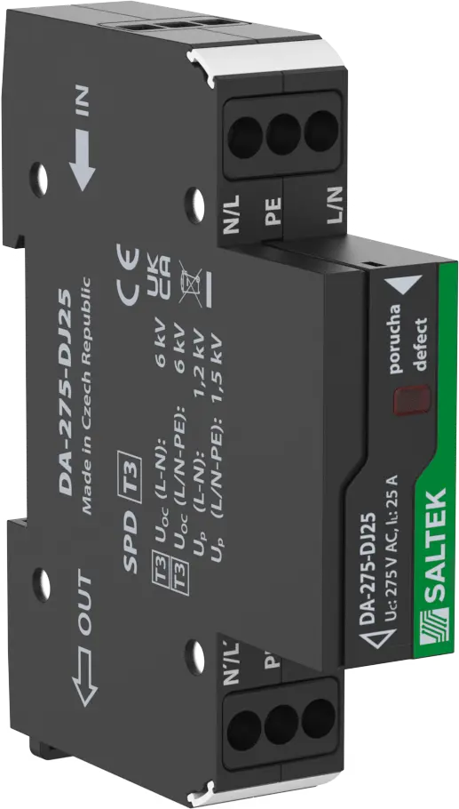
visual fault signalling
- universally applicable serially connected SPD for all types of LV electric and electronic equipments against surge voltage
- installation to LV installations, close to protected equipment
- for protection of the equipments against impact of induced overvoltages during a lightning strike or switching overvoltages


Technical parameters
| Parameter name | Parameter value | |
|---|---|---|
| Type of SPD | T3 | |
| Mounting | DIN rail 35 mm | |
| Nominal voltage | Un | 230.00 V AC |
| Maximum operating voltage | Uc | 275.00 V AC |
| Nominal load current | IL | 25.000 A |
| Type of network | TN | |
| Maximum overcurrent protection | 32 A gL/gG or C 32 A | |
| Short-circuit current rating | ISCCR | 6.0 kA |
| Nominal discharge current (8/20 µs) L-N | In | 3.00 kA |
| Nominal discharge current (8/20 µs) L+N-PE | In | 5.00 kA |
| Nominal discharge current (8/20 µs) N-PE | In | 3.00 kA |
| Test voltage L-N | Uoc | 6.0 kV |
| Test voltage L+N-PE | Uoc | 10.0 kV |
| Test voltage N-PE | Uoc | 6.0 kV |
| Voltage protection level mode L-N | Up | 1.20 kV |
| Voltage protection level mode L-PE | Up | 1.50 kV |
| Voltage protection level mode N-PE | Up | 1.50 kV |
| Response time L-N | ta | 25 ns |
| Response time N-PE | ta | 100 ns |
| TOV 5 s L-N | 335 V | |
| TOV 5 s L-PE | 440 V | |
| TOV characteristic (TOV 5 s) | withstand | |
| TOV 120 min L-N | 440 V | |
| TOV 120 min L-PE | 335 V | |
| TOV characteristic (120 min) | withstand | |
| TOV 200 ms L-PE | 1 200 V | |
| TOV 200 ms N-PE | 1 455 V | |
| TOV characteristic (TOV 200 ms) | safe failure | |
| Cross-section of connected conductors solid (max) | 6.00 mm2 | |
| Cross-section of connected conductors stranded (max) | 6.00 mm2 | |
| Fault indication | red indicator | |
| Degree of protection | IP 20 | |
| Range of ambient temperatures (min/max) | -40 / 80 °C | |
| Humidity | 5 - 95 % | |
| According to standard | EN 61643-11:2012, IEC 61643-11:2011 | |
| ETIM Class | EC000942 | |
| Customs tariff number | 85363030 | |
| EAN | 8595090557708 |
Files for download
-
Product dimensions
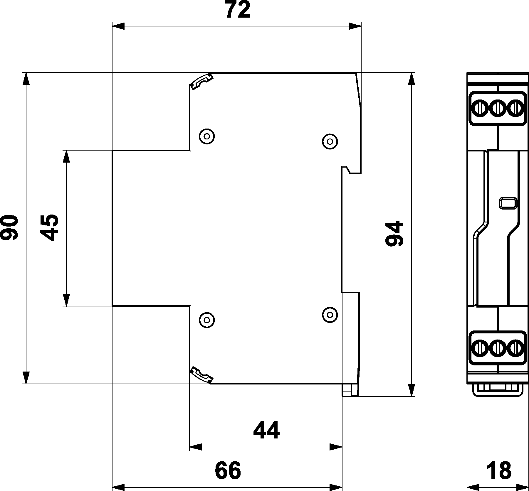
-
Basic circuit diagram